 feed
feed
After building out the USBtinyISP kit, I found it cumbersome to have to remember the pin out of the 6 pin ISP header and map that to the proper pins on the ATTinyXX series microcontroller. I'm of the camp that things should be made simple and easy to use. Especially repetitive tasks that could be prone to human error.
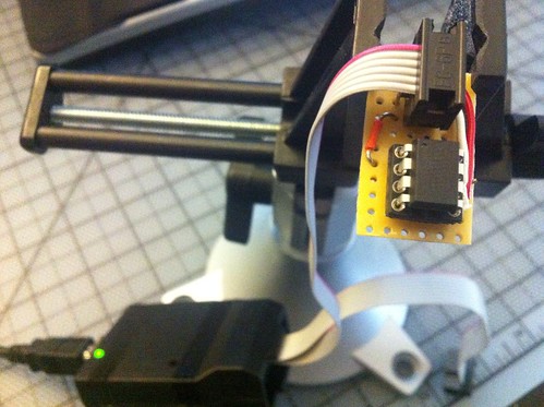
What does the cradle look like?
Pinouts
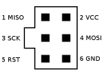
6 pin ISP header
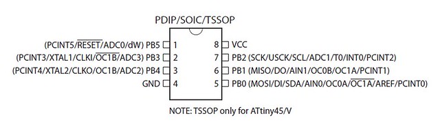
ATTiny 25/45/85
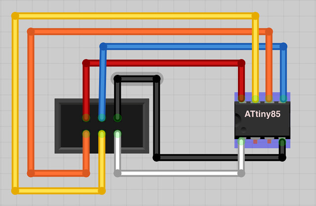
Wiring Diagram
Some photos of my implementation


I decided to use a wire wrapping socket that I dremeled down to 8 pins. This is nice so the legs are long enough to go into a breadboard. Super useful when prototyping and troubleshooting.

The cradle in action on a breadboard.
Inspiration and a couple of the diagrams in this post have come from here and here. I think for a project like this it would be useful to be able to make my own printed circuit boards. I've put it on my todo list and I hope to get to it soon.
Happy Hacking.